| Modifying a Versa-Vise |
By Jerry Crawford, Alfred Maine
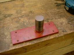
For as long as I've been doing my apprenticeship on long guns I've been struggling with the problem how to hold irregular shaped gun parts securely without damage. Last year at Friendship I saw a converted gyro-vise with a swivel back jaw that took care of all that. Then I spotted a "Gyro-Vise" on eBay. It was missing the base and had been slightly abused but I bid $25 and it was mine. The first thing I did was make a pedestal for it with a piece of plate and a few inches of 1½" diameter CRS bar. I made the post high enough so the vise sets a little closer to my focal point when working on a stock. I use this screwed on my bench at Friendship.
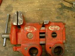
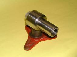
To replace the back jaw I hack sawed off most of it then put the frame in a milling machine and surfaced off the whole top of the vise frame. In the picture (above right) you can see the original shape of the frame and the modified frame together after the jaw was machined off. Gives you an idea how much you need to remove.
After milling the top flat I moved in 2", on center, from the left front edge and drilled and taped for a ½"-16 shoulder bolt that will act as the pivot for the new rear jaw. The front jaw, on the slide mechanism, needs to have a new face applied that will match the height/width of rear jaw plate. I countersunk two ¼-20 machine screws from the face. I plan on using a leather pad in mine so the aluminum will work. Nylon from an old cutting board or wood are alternatives.
I had already made the rear pivoting jaw seen below from a piece of 4" heavy wall angle iron and so the pivot bolt hole was a know dimension. When I made this shoulder bolt from a piece of hex stock I knew the tolerance I needed to work to for the right fit. Yours may be different - but the theory will be the same. The bolt shoulder (B) is .015" longer than the thickness of the angle plate you’re using for a back jaw. This will allow the bolt to seat tightly on the frame and the jaw to be solidly supported by the vise. This tolerance will let the jaw swivel yet not be sloppy or rocky. I had to make three shoulder bolts before I was satisfied. For the record here are my dimensions:
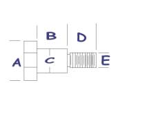
A = 1" hex bar. Any CRS will work but 10L42 machines like butter.
B = .643" which is .015" longer than the thickness of angle iron plate used for the jaw.
C = .622" (close tolerance sliding fit in a ⅜” diameter hole).
D = .820" Not a critical dimension but it can't be too long or it binds on the front jaw slide. Too short and it lacks "meat" to hold the jaw securely.
E = 1/2-16 thread.
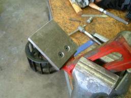
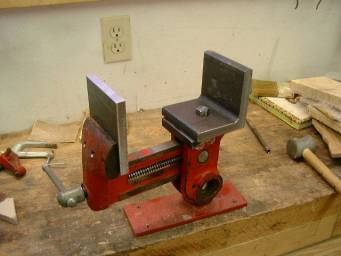
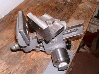
The rear swiveling jaw was a slice of 4" heavy wall angle iron. It was milled square & with parallel surfaces where there was metal to metal contact. The pivot hole in was located and machined before I turned down the hex shoulder bolt above. I gained over 2" of "grab" when I rotated the jaw 180 degrees. Pictured here the jaws are not machined down to final width or height. This is an intermediate assembly just to make sure it all works together. I found that my shoulder bolt, when tight, just touched the sliding casting from the front jaw mechanism so I needed to pull the bolt and file it down just a smidgen.
Once the mechanics of the vise was working the next item was the tilting axis potential. Originally this vise had an optional accessory that allowed the vise to tilt on a vertical axis as well as rotate around the bench post a full 360 degrees. The accessory arm fit the bench post and multiplied the useful range of motion of the vise significantly. This, then, allowed carving and engraving in the round at a comfortable angle without having to remove and reseat the work piece in the vise for the convenience of the craftsman. My tilt arm dimensions fit the American made vise and most vises made off-shore. However I recently worked on a Parrott from Grizzly Tool Company. It had to be finessed to accept the tilt arm by cleaning up the Chinese inch & a half milling in the three base holes with a Dremel tool and drum sander.
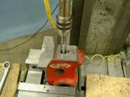
The vise worked beautifully on the tilt arm accessory but presented me with another problem. As designed the vise has a cam under the front jaw slide that bears against the bench post to hold the vise ridged when you tighten up on the work piece. It’s a very clever design. However, when the vise is used on the tilt arm the vise is in free fall until you tighten up the vise screw to secure the work piece. This is a very awkward and unwieldy situation and may have been the reason the original tilt arm was abandoned by users. There had to be some way to steady the vise while on the tilt arm so you had both hands free to position the work piece and tighten the vise screw. My solution was to drill and tap a ⅜-13 hole in the back of the casting for a lock screw.
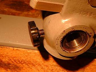
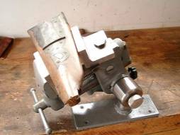
I put a black plastic knob on the machine cap screw and threaded it in place (above). The tightened screw holds the vise in any tilted position while I fiddle putting in the work piece and it just adds to the security of the vise when the internal cam is activated by tightening the vise screw. If I wish to adjust the tilt angle of the work piece it is only necessary to loosen the set knob and vise screw slightly and adjust. The work piece stays in place. It’s a simple and elegant solution anyone with a drill press and set of taps can make.
When fit and function were proper I disassembled the vise a final time and machined down the new jaws to a more esthetic size and shape. A professional machinist would chide me for my unorthodox planning & process of work but this system works for me. I reduced the width of the new jaws to the original and the height to a little over 2 inches. Any more than that is just in the way and objects near the top are further away from the vise screw than needed for mechanical advantage.
Some years ago these vises were fairly common and called Gyro-vise (the name on my label). I think it's even been marketed as a Versa-vise. Anymore if you want one you have to pony up over two hundred bucks to Brownell’s and they call it a Multi-vise. I learned recently that Woodcraft is selling this vise as a “Universal Vise” for under $50 and Grizzly has them available as the Parrott. At these prices you can rebuild it and have a darn nice gun making vise on your bench. They are very simply designed and manufactured but tuned up they are good, robust vises and have a long history in the gun making community.
Total cost for this project was about $40 and some pieces of iron from the school scrap bin. All of the machining work shown here was done in the Machine Trades class room at the Sanford Maine Vo-Tech high school where I take an occasional night course. I would judge the degree of difficulty to do this job is within the range of skill, knowledge and ability for most hobbyist gun makers. This whole modification took me about ten hours of shop time but a whole lot more hours of sketching, brainstorming and prototype making various parts until it all fell together. It’s all pretty elementary machining. But, if you make that shouldered pivot bolt from scratch and it turns out perfect you can be very proud of your effort. I certainly was.
This article is Copyright 2004 by Jerry Crawford and is published with the permission of the author .
| American Longrifles Home | Back | Gun Building Home |
This page was last updated on 02/13/04 .